Difference between revisions of "Pellet Extruder for 3D Printing"
(→4.Pruebas de eficiencia térmica) |
(→Advice) |
||
| (168 intermediate revisions by 7 users not shown) | |||
| Line 1: | Line 1: | ||
| − | [[category: | + | [[category:Ongoing projects]] |
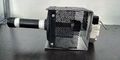
| − | [[File: | + | [[File:Pellet 3D printer 005.jpg|300px|thumb|Pellet 3D printer]] |
| − | [[File: | + | [[File:Pellet 3D printer 002.jpg|200px|thumb|Pellet Extruder]] |
| + | [[File:Pellet 3D printer 003.jpg|200px|thumb|Printing Area]] | ||
| + | |||
| + | Translated version of the project "[[Extrusor de Pellets para Impresión 3D]]" | ||
== Project Manager == | == Project Manager == | ||
| − | * [https:// | + | {| class="wikitable sortable collapsible" |
| + | ! Maker | ||
| + | ! Photo | ||
| + | ! Profile | ||
| + | |- | ||
| + | | [[Bustos Fabian]] (Project Manager)|| [[File:Fabian.jpg|Fabian.jpg]] || | ||
| + | *[https://utopiamaker.com/m3duto/user:197823 English .] | ||
| + | |- | ||
| + | |} | ||
== Introduction == | == Introduction == | ||
| − | + | After some years the FDM 3D printing patents and digital fabrication methods were released, the community started to discuss the fact that this industry is getting stuck, that FDM 3D printing is just a hobbie and a method for rapid protyping but not for serious applications in the serial production of products, due to this comments and bad publicity the members and developers of this project found a new way to change this reality, at this point the majority of 3d printing machines have three major problems to analyze and solve. | |
| + | |||
| + | The first problem is about printing volume, when thinking about printing large objects the major limit is the cost of the material, if a printing session of a large object uses more than 2 rolls of filament the printing method can be discarded due to the cost and replaced by another techniques, this means that the 3D printing community fell into the consumption culture of inkjet printers for example, where the "brands" make more money by selling expensive cartridges of ink and tonners than by selling the actual paper printers. | ||
| + | |||
| + | The second problem is about printing time, due to the large list of coordinate movements that the machine executes to finish one model, the sum of this small portions of material deposed and time makes this FDM technology unsuitable for serial production or could even be seen as non-rapid prototyping method in some cases, analyzing the posibilities for upgrading a printing head to use a diferent technique of deposition, the solution points to increase the amount of plastic deposed versus time. | ||
| + | |||
| + | The third but not final problem depicted here, is the linearity of the materials, it means that if you have only one roll of white PLA plastic, you can only print white PLA models, if you want to make pieces of another color or if you want to make a model of multiple colors, you have to buy the same amount of rolls of plastic, its a good business model for the companies that release this technology for free to the people, but at the same time there is a huge economic interest which works effectively. | ||
| + | |||
| + | [https://www.youtube.com/watch?v=geIKnWPlsOI&feature=youtu.be FM3D Pellet Extruder (In Spanish)] | ||
| + | |||
| + | == Project Colaborators == | ||
| + | {| class="wikitable sortable collapsible" | ||
| + | ! Maker | ||
| + | ! Photo | ||
| + | ! Profile | ||
| + | |- | ||
| + | | [[Duran Miguel]] (Assembly Assistant) || [[File:br_914883_photo.jpg|br_914883_photo.jpg]] || | ||
| + | *[https://utopiamaker.com/m3duto/user:914883 English .] | ||
| + | |- | ||
| + | | [https://es.utopiamaker.com/m3duto/uto_tpl_app.htm#!/one?userid=997037 Sebastian Martinez] (Assembly and Translation Assistant ) || [[File:Borra.jpg|125px|]] || | ||
| + | *[https://utopiamaker.com/m3duto/user:997037 English .] | ||
| + | |- | ||
| + | |} | ||
| + | |||
| + | == Problem #1: Printing Volume vs Cost == | ||
| + | |||
| + | Looking around the social media, we can see that the majority of 3D printing machines are capable to print inside a volume less than 30 x 30 x 30 cm, it's due to the fact that those small volumes are enough to cover the average consumer necessities, because the system is made in that way, but if a new series of big 3d printers become popular and the materials cheaper?, the users would switch automatically to print big scale projects and the consommation of plastic increases. Curiously if you want to make a model that occupies all the volume of your 3D printer, you have to pay a price of plastic even major to the cost of the machine, it's a sad reality if we think about all the plastic we put into the trash every week. | ||
| + | |||
| + | == Problem #2: Speed vs Productivity == | ||
| + | |||
| + | After some time of using 3D printers the regular user gets certain experience in the usage of the machines, their materials and ll the possiblities to obtain high quality pieces at the highest speed posible, sometimes not even taking care of the price of the tools or materials, the regular DIY 3D printer works with a printing head (extruder) which depose a thin hot filament on a building platform and draws the model layer by layer, with the mindset of quality the usage of small nozzles and deposing small volumes will always get a good result, but when the project becomes bigger and massive quantities of plastic have to be transformed, at this point the amount of spools of filament, the time that it could take to finish, and the delicate process of changing the filaments one spool after another. | ||
| + | |||
| + | == Problem #3: Material Versatility == | ||
| + | |||
| + | After this lapse of time the user that uses 3D printing to produce prototypes for engineering, toys or even prosthetic hands, it's easy to find around the work place empty spools of plastic with the hope of be rewinded, a box full of at least 5 kilo of failed prints saved as a treasure waiting the moment to be melted and reused, not to talk about a rainbow collection of plastic spools ready to create fantastic creations, every person who works with a 3D printer will always want to have unlimited posibilities of mixing colors and materials, maybe the necessity of generate complex models of materials with special properties to improve mechanical efficiency or high temp performance. | ||
| + | |||
| + | == Extruder Design == | ||
| − | + | To solve the problems cited before we propose the development of a Pellet Extruder Printing Head wich works with granulated plastic, the most valuable improvement over filament extruders is the low price per kilo of plastic, this plastic pellet can be found in 25 kilo packets whose costs are less than price of one roll of regular PLA, the industrial method to produce filament in china factories starts with this small balls of plastic, they put some additives and colorants to modify the properties and color of the final product, this generates some uncertainty about what are we melting on our machines, what kind of fumes they produce and the grade of biodegradability this materials really have, the use of a Pellet Extruder on a 3D printer gives total freedom of using your own colorants to match an specfic tone of color, you can add some well known additives to improve the properties of the final models and even make them stronger mixing some carbon fiber chips or steel powder inside, it's the idea of printing composite materials. | |
| − | + | There are already very good Pellet Extruders on the market ready to be installed on any xyz cartesian machine, but there is some different on the extruder we have to create, it's a mechanism that shortens the printing time, the system works with a Variable Width Nozzle, instead of using one fixed diameter hole at the output sharp point, we designed a plane metallic cap with a slit of 1x10mm, inside this slit we can find a moving piece that regulates the material output, the initial strategy to make it work faster than Filament Extruders is about using the small opening to mke the perimeters of the model, at the time of printing the infill it opens at the desired width or depending on the software to increase the printing volume and generate layers faster. The operation principle is the same that an industrial type plastic sheet extruder, but simplified to be installed in a moving shafts system. | |
| − | [ | + | A regular FDM 3D printer extruder is static and has a fixed diameter output nozzle, this Pellet Extruder generates a variable laminate which has the ability of rotating 360 degrees in order to adapt the orientation of the laminate to the contour of the models, the details of this process can be found in the [Mechanics] and Electronics section of this document. |
| − | |||
| − | |||
| − | |||
| − | |||
| − | |||
| − | |||
| − | |||
| − | |||
| − | |||
| − | |||
| − | |||
| − | |||
| − | + | <gallery> | |
| + | Extrusor_laminar_001.jpg|Nozzle´s side | ||
| + | Mech top.jpg|Nozzle's top | ||
| + | Boquilla cerrada.png|Closed Nozzle | ||
| + | Boquilla medio.png|50% Nozzle | ||
| + | Boquilla abierta.png|Opened nozzle | ||
| + | </gallery> | ||
| − | + | === Extruder Mechanics === | |
| − | |||
| − | |||
| − | |||
| − | |||
| − | |||
| + | The action strategy of the printing Tip is that when it is making outer perimeters the nozzle closes to let out a 1x1mm filament, that's how we can make the outer layers with good level of detailing, in the moment of filling the piece it opens up to 10mm wide and performs the work at least 6 times faster than a conventional extruder and when it is executing the displacements it closes completely to avoid unwanted extrusions before reaching the work coordinates. | ||
| − | + | <gallery> | |
| + | imp00.jpg|Nozzle close | ||
| + | imp11.jpg|Opening for Perimeter | ||
| + | imp22.jpg|Opening for Filling | ||
| + | nozzleseq1.png|Opening for Perimeter | ||
| + | nozzleseq2.png|50% Opening | ||
| + | nozzleseq3.png|75% Opening | ||
| + | nozzleseq5.png|100% Opening | ||
| + | </gallery> | ||
| − | + | === Extruder Electronics === | |
| − | + | ====Machine Firmware Modification==== | |
| − | |||
| − | |||
| − | |||
| − | + | Due to the changes made on the regular Pellet Extruder hardware, a correspondent circuit, firmware and software modification is necessary to make everything work in a synchronized way. Since the output Nozzle of the extruder generates a variable width flat filament and is able to twist 180 degrees to adapt itself to the contour of the trajectories, two additional motors have to be configured in the normal printer electronics system and programmed in the firmware. We use for the prototype printer a universal RAMPS board controlled by an Arduino Mega 2560 board, we keep the XYZE cartesian system connections, a secondary extruder driver is installed on the ramps board to control the Nozzle Amplitude. | |
| − | |||
| − | |||
| − | |||
| − | |||
| − | |||
| − | |||
| − | |||
| − | + | 15/01/2020 | |
| − | |||
| − | + | After testing different 3D printer control firmwares we decided that Sprinter is the most convenient program to modify due to their simplicity to control a cartesian 3D printer system, it was the most used 3d printed controller for ARDUINO/RAMPS boards until 2013, in the first image we can appreciate the workflow that the program uses to convert gcode commands into coordinate moves sequentially in a 3D printing session, in the second image we can see the modification necessary to make this new method of extrusion work. | |
| − | |||
| − | |||
| − | + | <gallery> | |
| + | Normal Sprinter Workflow.png|Normal Firmware Workflow | ||
| + | Sprinter Workflow modification 004.png|Firmware Workflow Modification | ||
| + | Firmware modification 18 11 2019_002.png|Custom angle calculation and positioning function | ||
| + | Pieza de prueba.jpg|Model for displacement Analisis | ||
| + | Lectura Raw de Angulo.jpg|Raw Angle Reading | ||
| + | Sprinter Workflow modification 005.png|Cold Extrusion Test | ||
| + | </gallery> | ||
| − | + | 31/01/2020 | |
| − | + | A custom Gcode (M93 Ax) was added to the firmware, this module receives an amplitude variable "x" wich ranges from 0 to 10mm, after some calculations it generates the pulses needed to open and close the output nozzle, when the system is wake up or after a reset is done, the default position of the nozzle's blocking rod is equal to zero and will be determined after by the commands received, this gcode calls will be generated automatically by the Slic3r software at especific moments of the printing session. | |
| + | <gallery> | ||
| + | Firmware modification 31 01 2020.png|Nozzle amplitude control code definition | ||
| + | </gallery> | ||
| + | |||
| + | == Assembly Manual == | ||
| + | ==== Disclaimer ==== | ||
| + | |||
| + | This is a Technical Tutorial for the construction of an Industrial Grade Device which means that only qualified and experienced personnel could execute and obtain the appropiate result without damage, if you dont feel in the capacity to perform the tasks I show in the following steps, dont worry, just find the appropiate place, the appropiate person and the appropiate tools to get it done, keep in mind that the most important thing is your integrity and security, this is not intended as a manual to harm yourself in the process, be careful with the instructions, try to make this work in a good mood and mind clear of alcohol or any other product that could affect your performance, I dont take any responsibility of the use of this information. | ||
| + | |||
| + | ==== Bill of Materials ==== | ||
| − | 1 | + | {| class="wikitable" |
| + | |- | ||
| + | ! Quantity !! Article !! Detail !! Material | ||
| + | |- | ||
| + | | 1 || Water pipe Nipple || 1/2"(dia) X 3"(Long) double thread || Iron or Bronze | ||
| + | |- | ||
| + | | 1 || Water pipe cap || 1/2"(dia) round || Iron or Bronze | ||
| + | |- | ||
| + | | 1 || Floor Flange Fitting || 1/2" thread || Iron or Bronze | ||
| + | |- | ||
| + | | 1 || Auger bit || 5/8"(dia) X 3"(Long) || Iron | ||
| + | |- | ||
| + | | 1 || Square structural tube || 70mm x 70mm X 70mm (Long) || Iron | ||
| + | |- | ||
| + | | 1 || Nema 23 Stepper Motor || with 1:72 Gearbox|| N/A | ||
| + | |- | ||
| + | | 1 || Rigid Coupling || 5mmdia to 12mmdia (for bit and motor shafts) || Iron or Aluminium | ||
| + | |- | ||
| + | | 1 || Band Resistive Heater || 12v 90Watts 28mm(dia) X 30mm(Long) || N/A | ||
| + | |- | ||
| + | | 1 || Thermistor || EPCOS 100K || N/A | ||
| + | |- | ||
| + | | 1 || Kapton Tape || 30mm width || Example | ||
| + | |- | ||
| + | | 1 || Teflon Tape|| Industrial grade || PTFE | ||
| + | |- | ||
| + | | 2 || Metal Mesh || Square 10x10cm || Iron or Aluminium | ||
| + | |} | ||
| − | === 2.Installing the electrical system === | + | <gallery> |
| + | Materiales.png|Materiales | ||
| + | Pipe-1.jpg|Water pipe | ||
| + | Pipe-2.jpg|80px|Water pipe cap | ||
| + | Metal-mesh.jpg|Metal Mesh 10x10cm square | ||
| + | Square structural tube.jpg|Square Structural Tube | ||
| + | Floor-flange.jpg|Floor-flange | ||
| + | |||
| + | </gallery> | ||
| + | |||
| + | {| class="wikitable" | ||
| + | |- | ||
| + | ! Electric Tools !! Manual Tools | ||
| + | |- | ||
| + | | Multimeter || Slot and Philips Screwdrivers | ||
| + | |- | ||
| + | | Drill || Pliers | ||
| + | |- | ||
| + | | Drill Bits || Pipe Wrench | ||
| + | |- | ||
| + | | 1" Saw Cup for Metal || Slim-Jaw Adjustable Wrench | ||
| + | |- | ||
| + | | Angle Grinder || Allen Key Set | ||
| + | |- | ||
| + | | Soldering Iron || Thread Tap M6 | ||
| + | |} | ||
| + | |||
| + | ====Advice==== | ||
| + | |||
| + | Before we start, there is something that we have to understand, is the fact that we are dealing with high density thermoplastics, those materials need high temperatures and lots of force to manipulate, it means that all the mechanics we are going to build here will be made out of metal, because of this, hard work with "heavy tools" are needed, the material I've succesfully used is iron due to their ideal heath transfer properties for this project, avoid of use alluminum, if it is a problem for you to find iron parts you can use bronze instead which has been proven to give good result. | ||
| + | |||
| + | {| class="wikitable" | ||
| + | |- | ||
| + | ! Step !! Description !! Tools needed !! Image guide | ||
| + | |- | ||
| + | | 1 || Cut 70mm of structural square tube of 70mm by 70mm, this cube will serve as container and the chassis of the extruder, use security glasses and gloves to protect yourself.|| Angle grinder with metal cutting disc. || | ||
| + | [[File:Step1 grindercut.jpg|100px|thumb|Angle grinder cut]] | ||
| + | |- | ||
| + | | 2 || Mark down and drill a 1" hole in the center on one surface and the opposite side, use oil or parafine to lubricate the tool frequently, the Auger bit will cross through this two holes, attached to the motor on the top and inside the nipple pipe at the bottom. || Drill with 1" Cup Saw ||[[File:Step2_drillhole.jpg|100px|thumb|Cup Saw Cutting Holes]] | ||
| + | |- | ||
| + | | 3 || Take the measurement of the distance between the holes of the motor and the floor flange, mark down the and drill the holes with the correspondent screw diameters || Drill and Drill bits || [[File:Step3_drillhole.jpg|100px|thumb|Screw Holes Drilling]] | ||
| + | |- | ||
| + | | 4 || Attach the floor flange with the screws and auto-lock nuts to join the two parts, be aware of the alignement of the big holes to ensure good rotation of the mechanism in the following steps. || Allen Keys or the tool that correspond the screws || [[File:Step4 place screws.jpg|100px|thumb|Screws in Place]] | ||
| + | |- | ||
| + | | 5 || Roll some teflon tape around the threads of the nipple pipe and screw the pipe cap on one side and the reservoir on the another, the tape will avoid plastic leaks that could occurr at high temperature. || Teflon tape and pipe wrench ||[[File:Step5 install nipple tip.jpg|100px|thumb|NIpple Pipe and Cap Assembled]] | ||
| + | |} | ||
| + | |||
| + | <gallery> | ||
| + | Parts to assemble.jpg|scheme of the pieces to assemble | ||
| + | Pipe and cap with teflon.jpg|Pipe and cap with teflon | ||
| + | Floor flange installed.jpg|Floor Flange installed | ||
| + | Base sheet installed.jpg|Top View | ||
| + | Installed.jpg|thumb|Bottom View | ||
| + | Auger installed.jpg|Auger Installed | ||
| + | Mechanical assembly.jpg|Mechanical assembly (Front view) | ||
| + | Mechanical assembly2.jpg|Mechanical assembly (Back View) | ||
| + | 115410.jpg|Mechanical assembly | ||
| + | </gallery> | ||
| + | |||
| + | === Installing the electrical system === | ||
Install the heating element, the heat sensor and motor wiring, this is connected to the machine's controller board. | Install the heating element, the heat sensor and motor wiring, this is connected to the machine's controller board. | ||
| − | === | + | === Mechanical efficiency test === |
| − | From the computer, send commands to the controller board to verify | + | From the computer, send commands to the controller board to verify the correct movement of the pellets inside of the extruder, verify the speed and strength requirements. |
| + | |||
| + | === Thermal efficiency test === | ||
| + | From the computer, send commands to the controller board to verify the heating element performance and define the optimal temperature to melt the plastic and make it flow through the tube. | ||
| + | |||
| + | === Material flow test === | ||
| + | Heat the extruder to the work temperature obtained before, and define the motor's speed to produce a continuos string of plastic as fast as possible, maintaining the diameter and the material properties. In this step the lenght and material's retraction time are calculated, to get total control of the extrusion during an impression. | ||
| − | === | + | === 3D Printer integration === |
| − | |||
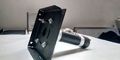
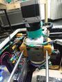
| − | + | A cubic 30x30x30cm Kondoro machine chasis has been modified to fit the extruder inside, the mechanical arrangement of the X and Y axis was made temporarily out of wood and plastic ties meanwhile the final adjustments got done and the final 3D design reached the final version, at the end we | |
| − | + | In order to make this extruder work on a cartesian XYZE system we had to adapt our electronics and modify the Firmware of the microcontroller to add two extra actuators to the extruder to control the output flow and the orientation of the nozzle. | |
| − | + | 24/06/2019 | |
| − | + | ||
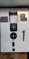
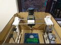
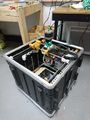
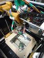
| + | *We have built a second printer that we will use exclusively for the development of the sheet extruder, it has a print volume of 300x400x300 mm, it was built using recycled materials, a whiskey box for the extruder and motors extracted from a paper printer, we use beer cans and resistive material from an old toaster for the heating element of the extruder. | ||
| − | |||
| − | |||
| − | |||
| − | |||
<gallery> | <gallery> | ||
| − | + | Piezas pellet printer.jpg|New Pieces Designed | |
| − | + | ExtruderAssembly 001.jpg|Printed parts Assembly | |
| − | + | ExtruderAssembly 002.jpg| | |
| − | |||
| − | |||
| − | |||
</gallery> | </gallery> | ||
| − | |||
| − | |||
| − | + | == Calibration and Testing == | |
| + | |||
| + | |||
| + | 10/06/2019 | ||
| + | |||
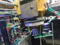
| + | Since the first assembly of the extruder, we used a Nema 17 motor of 2,2kg/cm Torque and 1:50 gearbox, which presented printing failures and loss of steps due to overheating, which also affected printing speed, something visible in the quality of the printed pieces, to solve this problem the motor has been replaced with a Nema 23 with 9 kg/cm torque and 1:72 gearbox, after the software adjustments and some tests, the extruder presented a better speed and acceleration control, and an improved print quality. | ||
<gallery> | <gallery> | ||
| − | + | Oldmotor.jpg|Extruder with Nema motor 17 1:50 | |
| − | + | Motorupgrade02.jpg|Extruder with Nema motor 23 1:72 | |
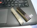
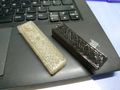
| − | + | Muestrapiezapelletsmotorupgrade.jpg|Piece Side View | |
| − | + | Muestrapiezapelletsmotorupgrade02.jpg|Piece Up View | |
| − | + | Motorupgrade.jpg|Print Test | |
| − | + | letraKpelletsavisoutopia.jpg|Print test | |
| − | |||
</gallery> | </gallery> | ||
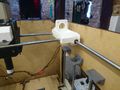
| − | + | 17/01/2020 | |
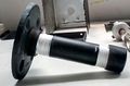
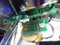
| − | + | During the print test of the new mechanism a heating problem was found, at the moment of setting the working temperature of the extruder, the motor support transfers heat from the nozzle to the motor that opens and closes the nozzle, this generates a loss of energy on the extruder cannon and blocks the motor movement, this metallic part was replaced with a piece made out of circuitboard fiberglass material, this should be enough to isolate the motor and keep the temperature concentrated on the tip and the tube of the extruder. | |
| − | + | TODO: Finish the assembly and continue the testing process, to ensure the proper heat transfer on the tube and motor heat isolation. | |
<gallery> | <gallery> | ||
| − | + | Motor support modification.jpg|Nozzle Width Motor Support Replacement | |
| − | + | Motor Support Modification 002.jpg| | |
| − | |||
| − | |||
| − | |||
| − | |||
| − | |||
| − | |||
| − | |||
</gallery> | </gallery> | ||
| − | + | 18/01/2020 | |
| − | 10/ | + | |
| − | * | + | A revision of the entire system was made today with the next observations: |
| + | |||
| + | *The extruder heater is working efficiently, reaching the working temperature (200 Celsius degrees) in a lapse of time of 10 minutes, this is the minimum time for the temperature to distribute gradually along the tube using the 60% of the heater power capacity. | ||
| + | *The isolation material used to protect the amplitude motor is working very well, the temperature of this motor is always under 30 Celsius degrees. | ||
| + | *The angle positioning is taking at least 3 second per degree due to the mechanical gearbox that multiplies the pulses by a factor of 50 and the response frequency of the motor. | ||
| + | *The X axis motor executes smooth movements of the extruder using low acceleration values (200 mm/s^2), the vibration of the print head depends directly of the acceleration. | ||
| + | TODO: | ||
| + | *A firmware modification has to be done to correct the trajectory, because the slot generated by opening the nozzle is not centered. | ||
| + | *The angle motor has to be replaced with a Nema 23 stepper, wich has enough speed and torque to control the nozzle angle, despite of the additional weight to the extruder. | ||
| + | *The steps per millimeter of the new angle motor have to be tuned. | ||
| + | *The steps per millimeter of the amplitude motor have to be tuned. | ||
| + | |||
| + | 29/01/2019 | ||
| − | + | <gallery> | |
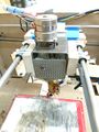
| − | + | Pellet 3D printer 005.jpg|Pellet 3D printer | |
| − | + | Pellet 3D printer 004.jpg| | |
| − | + | Pellet 3D printer 003.jpg| | |
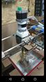
| + | Pellet 3D printer 002.jpg| | ||
| + | Pellet 3D printer 001.jpg| | ||
| + | </gallery> | ||
| − | + | == Reports & TS == | |
| − | + | Reports & TS in spanish [[Extrusor de Pellets para Impresión 3D]] | |
| − | |||
Latest revision as of 15:29, 16 April 2022


Translated version of the project "Extrusor de Pellets para Impresión 3D"
Contents
Project Manager
| Maker | Photo | Profile |
|---|---|---|
| Bustos Fabian (Project Manager) |  |
Introduction
After some years the FDM 3D printing patents and digital fabrication methods were released, the community started to discuss the fact that this industry is getting stuck, that FDM 3D printing is just a hobbie and a method for rapid protyping but not for serious applications in the serial production of products, due to this comments and bad publicity the members and developers of this project found a new way to change this reality, at this point the majority of 3d printing machines have three major problems to analyze and solve.
The first problem is about printing volume, when thinking about printing large objects the major limit is the cost of the material, if a printing session of a large object uses more than 2 rolls of filament the printing method can be discarded due to the cost and replaced by another techniques, this means that the 3D printing community fell into the consumption culture of inkjet printers for example, where the "brands" make more money by selling expensive cartridges of ink and tonners than by selling the actual paper printers.
The second problem is about printing time, due to the large list of coordinate movements that the machine executes to finish one model, the sum of this small portions of material deposed and time makes this FDM technology unsuitable for serial production or could even be seen as non-rapid prototyping method in some cases, analyzing the posibilities for upgrading a printing head to use a diferent technique of deposition, the solution points to increase the amount of plastic deposed versus time.
The third but not final problem depicted here, is the linearity of the materials, it means that if you have only one roll of white PLA plastic, you can only print white PLA models, if you want to make pieces of another color or if you want to make a model of multiple colors, you have to buy the same amount of rolls of plastic, its a good business model for the companies that release this technology for free to the people, but at the same time there is a huge economic interest which works effectively.
FM3D Pellet Extruder (In Spanish)
Project Colaborators
| Maker | Photo | Profile |
|---|---|---|
| Duran Miguel (Assembly Assistant) |  |
|
| Sebastian Martinez (Assembly and Translation Assistant ) |  |
Problem #1: Printing Volume vs Cost
Looking around the social media, we can see that the majority of 3D printing machines are capable to print inside a volume less than 30 x 30 x 30 cm, it's due to the fact that those small volumes are enough to cover the average consumer necessities, because the system is made in that way, but if a new series of big 3d printers become popular and the materials cheaper?, the users would switch automatically to print big scale projects and the consommation of plastic increases. Curiously if you want to make a model that occupies all the volume of your 3D printer, you have to pay a price of plastic even major to the cost of the machine, it's a sad reality if we think about all the plastic we put into the trash every week.
Problem #2: Speed vs Productivity
After some time of using 3D printers the regular user gets certain experience in the usage of the machines, their materials and ll the possiblities to obtain high quality pieces at the highest speed posible, sometimes not even taking care of the price of the tools or materials, the regular DIY 3D printer works with a printing head (extruder) which depose a thin hot filament on a building platform and draws the model layer by layer, with the mindset of quality the usage of small nozzles and deposing small volumes will always get a good result, but when the project becomes bigger and massive quantities of plastic have to be transformed, at this point the amount of spools of filament, the time that it could take to finish, and the delicate process of changing the filaments one spool after another.
Problem #3: Material Versatility
After this lapse of time the user that uses 3D printing to produce prototypes for engineering, toys or even prosthetic hands, it's easy to find around the work place empty spools of plastic with the hope of be rewinded, a box full of at least 5 kilo of failed prints saved as a treasure waiting the moment to be melted and reused, not to talk about a rainbow collection of plastic spools ready to create fantastic creations, every person who works with a 3D printer will always want to have unlimited posibilities of mixing colors and materials, maybe the necessity of generate complex models of materials with special properties to improve mechanical efficiency or high temp performance.
Extruder Design
To solve the problems cited before we propose the development of a Pellet Extruder Printing Head wich works with granulated plastic, the most valuable improvement over filament extruders is the low price per kilo of plastic, this plastic pellet can be found in 25 kilo packets whose costs are less than price of one roll of regular PLA, the industrial method to produce filament in china factories starts with this small balls of plastic, they put some additives and colorants to modify the properties and color of the final product, this generates some uncertainty about what are we melting on our machines, what kind of fumes they produce and the grade of biodegradability this materials really have, the use of a Pellet Extruder on a 3D printer gives total freedom of using your own colorants to match an specfic tone of color, you can add some well known additives to improve the properties of the final models and even make them stronger mixing some carbon fiber chips or steel powder inside, it's the idea of printing composite materials.
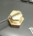
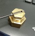
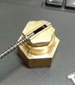
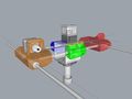
There are already very good Pellet Extruders on the market ready to be installed on any xyz cartesian machine, but there is some different on the extruder we have to create, it's a mechanism that shortens the printing time, the system works with a Variable Width Nozzle, instead of using one fixed diameter hole at the output sharp point, we designed a plane metallic cap with a slit of 1x10mm, inside this slit we can find a moving piece that regulates the material output, the initial strategy to make it work faster than Filament Extruders is about using the small opening to mke the perimeters of the model, at the time of printing the infill it opens at the desired width or depending on the software to increase the printing volume and generate layers faster. The operation principle is the same that an industrial type plastic sheet extruder, but simplified to be installed in a moving shafts system.
A regular FDM 3D printer extruder is static and has a fixed diameter output nozzle, this Pellet Extruder generates a variable laminate which has the ability of rotating 360 degrees in order to adapt the orientation of the laminate to the contour of the models, the details of this process can be found in the [Mechanics] and Electronics section of this document.
Nozzle´s side
Nozzle's top
Closed Nozzle
50% Nozzle
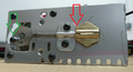
Opened nozzle


Extruder Mechanics
The action strategy of the printing Tip is that when it is making outer perimeters the nozzle closes to let out a 1x1mm filament, that's how we can make the outer layers with good level of detailing, in the moment of filling the piece it opens up to 10mm wide and performs the work at least 6 times faster than a conventional extruder and when it is executing the displacements it closes completely to avoid unwanted extrusions before reaching the work coordinates.
Nozzle close
Opening for Perimeter
Opening for Filling
Opening for Perimeter
50% Opening
75% Opening
100% Opening


Extruder Electronics
Machine Firmware Modification
Due to the changes made on the regular Pellet Extruder hardware, a correspondent circuit, firmware and software modification is necessary to make everything work in a synchronized way. Since the output Nozzle of the extruder generates a variable width flat filament and is able to twist 180 degrees to adapt itself to the contour of the trajectories, two additional motors have to be configured in the normal printer electronics system and programmed in the firmware. We use for the prototype printer a universal RAMPS board controlled by an Arduino Mega 2560 board, we keep the XYZE cartesian system connections, a secondary extruder driver is installed on the ramps board to control the Nozzle Amplitude.
15/01/2020
After testing different 3D printer control firmwares we decided that Sprinter is the most convenient program to modify due to their simplicity to control a cartesian 3D printer system, it was the most used 3d printed controller for ARDUINO/RAMPS boards until 2013, in the first image we can appreciate the workflow that the program uses to convert gcode commands into coordinate moves sequentially in a 3D printing session, in the second image we can see the modification necessary to make this new method of extrusion work.

Normal Firmware Workflow
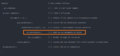
Firmware Workflow Modification
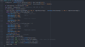
Custom angle calculation and positioning function
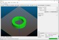
Model for displacement Analisis
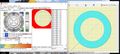
Raw Angle Reading
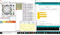
Cold Extrusion Test


31/01/2020
A custom Gcode (M93 Ax) was added to the firmware, this module receives an amplitude variable "x" wich ranges from 0 to 10mm, after some calculations it generates the pulses needed to open and close the output nozzle, when the system is wake up or after a reset is done, the default position of the nozzle's blocking rod is equal to zero and will be determined after by the commands received, this gcode calls will be generated automatically by the Slic3r software at especific moments of the printing session.
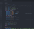
Nozzle amplitude control code definition

Assembly Manual
Disclaimer
This is a Technical Tutorial for the construction of an Industrial Grade Device which means that only qualified and experienced personnel could execute and obtain the appropiate result without damage, if you dont feel in the capacity to perform the tasks I show in the following steps, dont worry, just find the appropiate place, the appropiate person and the appropiate tools to get it done, keep in mind that the most important thing is your integrity and security, this is not intended as a manual to harm yourself in the process, be careful with the instructions, try to make this work in a good mood and mind clear of alcohol or any other product that could affect your performance, I dont take any responsibility of the use of this information.
Bill of Materials
| Quantity | Article | Detail | Material |
|---|---|---|---|
| 1 | Water pipe Nipple | 1/2"(dia) X 3"(Long) double thread | Iron or Bronze |
| 1 | Water pipe cap | 1/2"(dia) round | Iron or Bronze |
| 1 | Floor Flange Fitting | 1/2" thread | Iron or Bronze |
| 1 | Auger bit | 5/8"(dia) X 3"(Long) | Iron |
| 1 | Square structural tube | 70mm x 70mm X 70mm (Long) | Iron |
| 1 | Nema 23 Stepper Motor | with 1:72 Gearbox | N/A |
| 1 | Rigid Coupling | 5mmdia to 12mmdia (for bit and motor shafts) | Iron or Aluminium |
| 1 | Band Resistive Heater | 12v 90Watts 28mm(dia) X 30mm(Long) | N/A |
| 1 | Thermistor | EPCOS 100K | N/A |
| 1 | Kapton Tape | 30mm width | Example |
| 1 | Teflon Tape | Industrial grade | PTFE |
| 2 | Metal Mesh | Square 10x10cm | Iron or Aluminium |
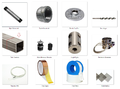
Materiales
Water pipe
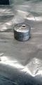
Water pipe cap
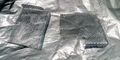
Metal Mesh 10x10cm square
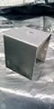
Square Structural Tube
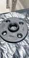
Floor-flange


| Electric Tools | Manual Tools |
|---|---|
| Multimeter | Slot and Philips Screwdrivers |
| Drill | Pliers |
| Drill Bits | Pipe Wrench |
| 1" Saw Cup for Metal | Slim-Jaw Adjustable Wrench |
| Angle Grinder | Allen Key Set |
| Soldering Iron | Thread Tap M6 |
Advice
Before we start, there is something that we have to understand, is the fact that we are dealing with high density thermoplastics, those materials need high temperatures and lots of force to manipulate, it means that all the mechanics we are going to build here will be made out of metal, because of this, hard work with "heavy tools" are needed, the material I've succesfully used is iron due to their ideal heath transfer properties for this project, avoid of use alluminum, if it is a problem for you to find iron parts you can use bronze instead which has been proven to give good result.
| Step | Description | Tools needed | Image guide |
|---|---|---|---|
| 1 | Cut 70mm of structural square tube of 70mm by 70mm, this cube will serve as container and the chassis of the extruder, use security glasses and gloves to protect yourself. | Angle grinder with metal cutting disc. | |
| 2 | Mark down and drill a 1" hole in the center on one surface and the opposite side, use oil or parafine to lubricate the tool frequently, the Auger bit will cross through this two holes, attached to the motor on the top and inside the nipple pipe at the bottom. | Drill with 1" Cup Saw | |
| 3 | Take the measurement of the distance between the holes of the motor and the floor flange, mark down the and drill the holes with the correspondent screw diameters | Drill and Drill bits | |
| 4 | Attach the floor flange with the screws and auto-lock nuts to join the two parts, be aware of the alignement of the big holes to ensure good rotation of the mechanism in the following steps. | Allen Keys or the tool that correspond the screws | |
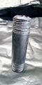
| 5 | Roll some teflon tape around the threads of the nipple pipe and screw the pipe cap on one side and the reservoir on the another, the tape will avoid plastic leaks that could occurr at high temperature. | Teflon tape and pipe wrench |


scheme of the pieces to assemble
Pipe and cap with teflon
Floor Flange installed
Top View
Bottom View
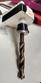
Auger Installed
Mechanical assembly (Front view)
Mechanical assembly (Back View)
Mechanical assembly


Installing the electrical system
Install the heating element, the heat sensor and motor wiring, this is connected to the machine's controller board.
Mechanical efficiency test
From the computer, send commands to the controller board to verify the correct movement of the pellets inside of the extruder, verify the speed and strength requirements.
Thermal efficiency test
From the computer, send commands to the controller board to verify the heating element performance and define the optimal temperature to melt the plastic and make it flow through the tube.
Material flow test
Heat the extruder to the work temperature obtained before, and define the motor's speed to produce a continuos string of plastic as fast as possible, maintaining the diameter and the material properties. In this step the lenght and material's retraction time are calculated, to get total control of the extrusion during an impression.
3D Printer integration
A cubic 30x30x30cm Kondoro machine chasis has been modified to fit the extruder inside, the mechanical arrangement of the X and Y axis was made temporarily out of wood and plastic ties meanwhile the final adjustments got done and the final 3D design reached the final version, at the end we In order to make this extruder work on a cartesian XYZE system we had to adapt our electronics and modify the Firmware of the microcontroller to add two extra actuators to the extruder to control the output flow and the orientation of the nozzle.
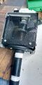
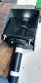
24/06/2019
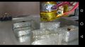
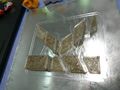
- We have built a second printer that we will use exclusively for the development of the sheet extruder, it has a print volume of 300x400x300 mm, it was built using recycled materials, a whiskey box for the extruder and motors extracted from a paper printer, we use beer cans and resistive material from an old toaster for the heating element of the extruder.
New Pieces Designed
Printed parts Assembly


Calibration and Testing
10/06/2019
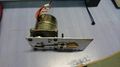
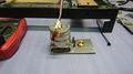
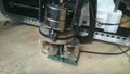
Since the first assembly of the extruder, we used a Nema 17 motor of 2,2kg/cm Torque and 1:50 gearbox, which presented printing failures and loss of steps due to overheating, which also affected printing speed, something visible in the quality of the printed pieces, to solve this problem the motor has been replaced with a Nema 23 with 9 kg/cm torque and 1:72 gearbox, after the software adjustments and some tests, the extruder presented a better speed and acceleration control, and an improved print quality.
Extruder with Nema motor 17 1:50
Extruder with Nema motor 23 1:72
Piece Side View
Piece Up View
Print Test
Print test


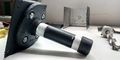
17/01/2020
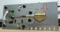
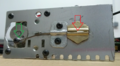
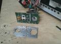
During the print test of the new mechanism a heating problem was found, at the moment of setting the working temperature of the extruder, the motor support transfers heat from the nozzle to the motor that opens and closes the nozzle, this generates a loss of energy on the extruder cannon and blocks the motor movement, this metallic part was replaced with a piece made out of circuitboard fiberglass material, this should be enough to isolate the motor and keep the temperature concentrated on the tip and the tube of the extruder.
TODO: Finish the assembly and continue the testing process, to ensure the proper heat transfer on the tube and motor heat isolation.
Nozzle Width Motor Support Replacement


18/01/2020
A revision of the entire system was made today with the next observations:
- The extruder heater is working efficiently, reaching the working temperature (200 Celsius degrees) in a lapse of time of 10 minutes, this is the minimum time for the temperature to distribute gradually along the tube using the 60% of the heater power capacity.
- The isolation material used to protect the amplitude motor is working very well, the temperature of this motor is always under 30 Celsius degrees.
- The angle positioning is taking at least 3 second per degree due to the mechanical gearbox that multiplies the pulses by a factor of 50 and the response frequency of the motor.
- The X axis motor executes smooth movements of the extruder using low acceleration values (200 mm/s^2), the vibration of the print head depends directly of the acceleration.
TODO:
- A firmware modification has to be done to correct the trajectory, because the slot generated by opening the nozzle is not centered.
- The angle motor has to be replaced with a Nema 23 stepper, wich has enough speed and torque to control the nozzle angle, despite of the additional weight to the extruder.
- The steps per millimeter of the new angle motor have to be tuned.
- The steps per millimeter of the amplitude motor have to be tuned.
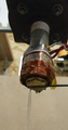
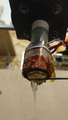
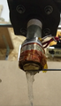
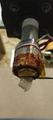
29/01/2019
Pellet 3D printer


Reports & TS
Reports & TS in spanish Extrusor de Pellets para Impresión 3D