Electronic Prostetic Arm
Contents
Project manager
| Maker | Image | Profile |
|---|---|---|
| Prashant Gade |

Project description
- Context: The Idea was about solving a problem that derails the lives of millions of people across the globe. The world is home to more than 22 million people with disabilities, with children making up nearly 8 million of that number. Due to the cost and lack of accessibility, most of these people never get the help they need. Today 80 % of all amputees are in developing countries. India alone is a home of more than 5 hundred thousand people living with no prosthetic care. Current prosthetic devices are advance and cost thousands of dollars and are not affordable in developing.
- Product descripction xxxxxxxxxxxxxxxxxxxxxxxxxxxxx xxxxxxxxxxxxxxxxxxxxxxxxxxxxxxxxxxxx xxxxxxxxxxxxxxxxxxxxxxxxxxxxxxxx xxxxxxxxxxxxxxxxxxxxxxxxxxxxxxxxxxxxx xxxxxxxxxxxxxxxxxxxxxxxxxxxxxxxxxxxxxxxxxxx xxxxxxxxxxxxxxxxxxxxxxxxxxxxxxx xxxxxxxxxxxxxxxxxxxxxxxxxxxxxxxx xxxxxxxxxxxxxxxxxxxxxxxxxxxxxxxxxxxxxx
- Short-term goals xxxxxxxxxxxxxxxxxxxxxxxxxxxxx xxxxxxxxxxxxxxxxxxxxxxxxxxxxxxxxxxxx xxxxxxxxxxxxxxxxxxxxxxxxxxxxxxxx xxxxxxxxxxxxxxxxxxxxxxxxxxxxxxxxxxxxx xxxxxxxxxxxxxxxxxxxxxxxxxxxxxxxxxxxxxxxxxxx xxxxxxxxxxxxxxxxxxxxxxxxxxxxxxx xxxxxxxxxxxxxxxxxxxxxxxxxxxxxxxx xxxxxxxxxxxxxxxxxxxxxxxxxxxxxxxxxxxxxx
Necessary resources
Human:
Fot the development of this unit, are needed student, profesionals engineers.
Materials:
- 1 X Water pipe Nipple 1/2"(dia) x 3"(long) double thread, Iron or Copper
- 1 X Water pipe cap 1/2"(dia) round, Iron or Copper
- 1 X Floor Flange Fitting 1/2" thread, Iron or Copper
- 1 X Auger bit 1/2"(dia) X 5"
Financials:
Water pipe
Water pipe cap
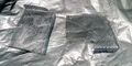
Metal Mesh 10x10cm square
Square Structural Tube
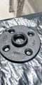
Floor-flange


Manual Tools:
- Slot and Philips Screwdrivers
- Pliers
- Pipe Wrench
- Slim-Jaw Adjustable Wrench
- Allen Key Set
- Thread Tap M6
Electric Tools:
- Multimeter
- Drill
  -Drill Bits
  -1" Saw Cup for Metal
- Angle Grinder
Stages
- 0. Disclaimer
- 1. Building the Mechanics
- 2. Installing the Electrical system
- 3. Mechanic Efficiency Test
- 4. Thermal Efficiency Test
- 5. Pruebas de fluidez del material
- 6. Integración a la impresora 3D
0.Disclaimer
This is a Technical Tutorial for the construction of an Industrial Grade Device which means that only qualified and experienced personnel could execute and obtain the appropiate result without damage, if you dont feel in the capacity to perform the tasks I show in the next steps, dont worry, just find the appropiate place, the appropiate person and the appropiate tools to get it done, keep in mind that the most important thing is your integrity and this is not intended as a manual to harm yourself in the process, be careful with the instructions, try to make this work in a good mood and mind clear of alcohol or any other product that could affect your performance, I dont take any responsibility of the use of this information.
1.Building the Mechanics

Before we start there is something that we have to understand, is the fact that we are dealing with high density thermoplastics, those materials need high temperatures and lots of force to manipulate, it means that all the mechanics we are going to build here will be made out of metal, because of this, hard work with "heavy tools" are needed, the material I've succesfully used is iron due to their ideal heath transfer properties for this project, avoid of use alluminum, if it is a problem for you to find iron parts you can use bronze instead which has been proven to give good result.
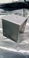
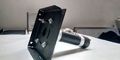
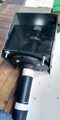
1.1 Cut 70mm of structural square tube of 70mm by 70mm, you can use the angle grinder with metal cutting disc, this cube will serve as container and the chassis of the extruder.
1.2 Use the Drill with the 1"Saw Cup to make two holes perfectly aligned at the center of the cube.
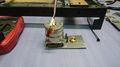
1.3 Place and center the flange in one hole, mark down the points where the screws will be placed, Place the motor on the other hole, carefully center the axle on the hole and mark down the points where the screws will support the motor.
1.4
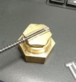
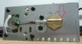
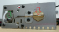
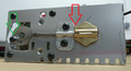
scheme of the pieces to assemble
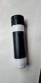
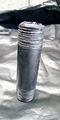
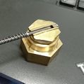
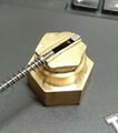
Pipe and cap with teflon
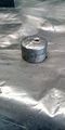
Floor Flange installed
Top View
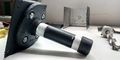
Bottom View
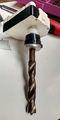
Auger Installed
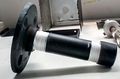
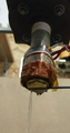
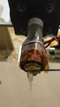
Mechanical assembly (Front view)
Mechanical assembly (Back View)


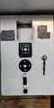
2.Installing the electrical system
Install the heating element, the heat sensor and motor wiring, this is connected to the machine's controller board.
3.Mechanical efficiency test
From the computer, send commands to the controller board to verify the correct movement of the pellets inside of the extruder, verify the speed and strength requirements.
4.Thermal efficiency test
From the computer, send commands to the controller board to verify the heating element performance and define the optimal temperature to melt the plastic and make it flow through the tube.
5.Material flow test
Heat the extruder to the work temperature obtained before, and define the motor's speed to produce a continuos string of plastic as fast as possible, maintaining the diameter and the material properties. In this step the lenght and material's retraction time are calculated, to get total control of the extrusion during an impression.
6.3D Printer integration
Use the temperature and displacement data to adjust the printer firmware parameters, this will be integrated to the machine and will always work as a normal extruder, the data will be used too in the software "slic3r" to generate G codes for the machine at different tempetatures, speeds, accelerations and retraction rates, make some test to adjust the settings for different models.
Additional advance
10/06/2019
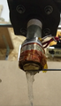
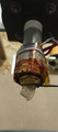
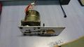
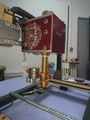
Since the first assembly of the extruder, we used a Nema 17 motor of 2,2kg/cm Torque and 1:50 gearbox, which presented printing failures and loss of steps due to overheating, which also affected printing speed, something visible in the quality of the printed pieces, to solve this problem the motor has been replaced with a Nema 23 with 9 kg/cm torque and 1:72 gearbox, after the software adjustments and some tests, the extruder presented a better speed and acceleration control, and an improved print quality.
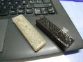
Extruder with Nema motor 17 1:50
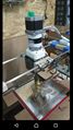
Extruder with Nema motor 23 1:72
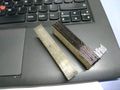
Piece Side View
Piece Up View
Print Test
Print test


23/05/2019
- We take as a fact that a big volume print is expensive and take a long time, until now we have achieved good performance on the Pellet Extruder using PLA pellets, which reduce the printing cost ten times compared with filament printing method.
To solve the printing time problem a variable volume printing nozzle has been designed, it's a extrusion tip that doesn't have a specific diameter orifice, it has a 1x10 mm groove. this one has a moving part that controls the material output at different times of the print. The operation principle is the same that an industrial type plastic sheet extruder has, but simplified to be installed in a moving shafts system. The action strategy of this printing Tip is that when it is making outer perimeters the nozzle closes to let out a 1x1mm filament, that's how we can make the outer layers with good level of detailing, in the moment of filling the piece it opens up to 10mm wide and performs the work at least 6 times faster than a conventional extruder and when it is executing the displacements it closes completely to avoid unwanted extrusions before reaching the work coordinates.
Nozzle close
Opening for Perimeter
Opening for Filling
Opening for Perimeter
50% Opening
75% Opening
100% Opening


24/06/2019
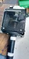
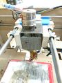
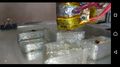
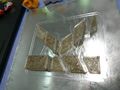
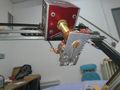
- We have built a second printer that we will use exclusively for the development of the sheet extruder, it has a print volume of 300x400x300 mm, it was built using recycled materials, a whiskey box for the extruder and motors extracted from a paper printer, we use beer cans and resistive material from an old toaster for the heating element of the extruder.
A stepper motor with gearbox has been installed on the tip of the extruder, which moves a rod along a groove with 10 mm wide and 1 mm diameter, this mechanism has been built entirely by hand with the help of a motortool and a manual drill.
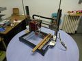
Sheet Printer front
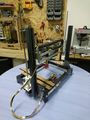
Sheet Printer Back
Nozzle´s side
Nozzle's top
Installed Nozzle
Installed Nozzle
Closed Nozzle
50% Nozzle
Open nozzle


Project Status
10/06/2019

- We designed the parts for the printer, to eplace the temporal parts, the machine will create this pieces in the second week of June
20/05/2019
- We are making simulation on Rhinoceros Grsshopper, for the Gcode generation.
- Post process tests have been done in Slic3r with Perl Language for the Gcode generation.
- A professional with knowledge in mathematics and programing is required for generate the codes that will make the extruder work properly.
24/06/2019
- A temporal Method to generate Gcode for the Machine with CNC software and manual edition for Gcode archives has been found.
- A professional with knowledge in mathematics and programing is required for generate the codes that will make the extruder work properly.
Activities
September 2019
Makers & assistants
Reports & TS
| miercoles 14 | Descripción | Tiempo | TS |
|---|---|---|---|
| Fabian Bustos | resume your work xxxxxxxxxxxxxxxxx xxxxxxxxxxxxxxxxxxxxxxxxxx xxxxxxxxxxxxxxxxxx xxxxxxxxxxxxxxxxxxxxxxxxxxxxxxx xxxxxxxxxxxxxxxxxxxxxxxxxxxx xxxxxxxxxxxxxxxxxxxxxxxxxx xxxxxxxxxxxxxxxxxxxxxxxxxxxxxxxxxxx | 40 mn | 2 TS |
| Assistant 1 | work | 20 mn | 1 TS |
| Maker 2 | resume work | 20 mn | 1 TS |
comments progress and planing
August 2019
Makers
Reports & TS
comments progress and planing