Difference between revisions of "Pellet Extruder for 3D Printing"
(→Avances Adicionales) |
(→Avances Adicionales) |
||
| Line 101: | Line 101: | ||
23/05/2019 | 23/05/2019 | ||
| − | We take as a fact that a big volume print is expensive and take a long time. | + | *We take as a fact that a big volume print is expensive and take a long time, until this moment we have achieved the right development of the Pellet Extruder using PLA pellets, which reduce the prinitng cost to one tenth in comparison with filament printing methood. |
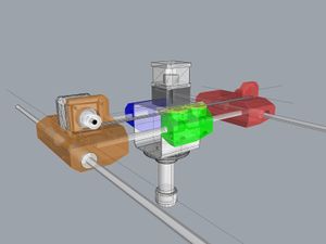
| − | + | To solve the printing time problem a variable volume printing nozzle has been designed, it's a extrusion tip that doesn't have a specific diameter orifice, it has a 1x1 cm groove. this one has a moving part that controlls the material output in different times of the print. The operation principle is the same that an Industrial Type Plastic sheet Extruder has, but simplified to be installed in a moving shafts system. | |
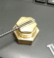
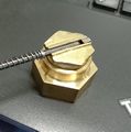
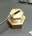
| − | + | The action strategy of this printing Tip is that when it is making outer perimeters the nozzle closes to let out a 1x1mm filament, that's how we can make the outer layers with good level of detailing, in the moment of filling the piece it opens up to 10mm and performs the work at least 6 times faster than a conventional extruder and when it is executing the displacements, it closes completely to avoid unwanted intrusions before reaching the work coordinates. | |
| − | |||
<gallery> | <gallery> | ||
| − | imp00.jpg| | + | imp00.jpg|Nozzle close |
| − | imp11.jpg| | + | imp11.jpg|Opening for Perimeter |
| − | imp22.jpg| | + | imp22.jpg|Opening for Filling |
| − | nozzleseq1.png| | + | nozzleseq1.png|Opening for Perimeter |
| − | nozzleseq2.png| | + | nozzleseq2.png|50% Opening |
| − | nozzleseq3.png| | + | nozzleseq3.png|75% Opening |
| − | nozzleseq5.png| | + | nozzleseq5.png|100% Opening |
</gallery> | </gallery> | ||
Revision as of 17:24, 31 July 2019
Contents
Project Manager
Introduction
The current 3D printing industry is being limited to volumes less than 30cm3, when thinking about printing large objects the major limit is the cost of the material, if a printing session of a large object uses more than 2 rolls of filament the printing method can be discarded due the high cost, a granulated plastic extruder decreases the cost of the material up to 10 times and has the additional advantage of printing with nozzles with diameters greater than 1mm, which increases the printing speed at least 3 times compared to the Filament printing, other great advantage of this method is the opportunity to put additives, colorants and chips of other materials like carbon fiber which generates strong printed parts of composite materials.
_____________________________________https://youtu.be/geIKnWPlsOI___________________________________
Bill of Materials
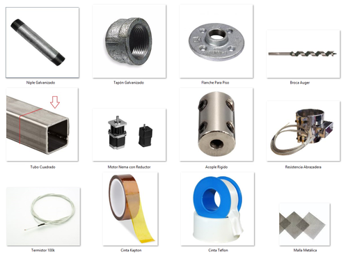
- 1 X Water pipe Nipple 1/2"(dia) x 3"(long) double thread, Iron or Copper
- 1 X Water pipe cap 1/2"(dia) round, Iron or Copper
- 1 X Floor Flange Fitting 1/2" thread, Iron or Copper
- 1 X Auger bit 1/2"(dia) X 5"
- 1 X Square structural tube 70mm x 70mm X 70mm (long), Iron
- 1 X Nema 23 Stepper Motor with 1:72 Gearbox
- 1 X Rigid Coupling 5mm to 12mm (for bit and motor shafts)
- 1 X Band Resistive Heater 12v 90Watts 28mm(dia) X 30mm(long)
- 1 X Thermistor EPCOS 100K
- 1 X Kapton Tape de 30mm width
- 1 X Teflon Tape
- 2 X Metal Mesh Square 10x10cm
Manual Tools:
- Slot and Philips Screwdrivers
- Pliers
- Pipe Wrench
- Slim-Jaw Adjustable Wrench
- Allen Key Set
- Thread Tap M6
Electric Tools:
- Multimeter
- Drill
  -Drill Bits
  -1" Saw Cup for Metal
- Angle Grinder
Stages
- 0. Disclaimer
- 1. Building the Mechanics
- 2. Installing the Electrical system
- 3. Mechanic Efficiency Test
- 4. Thermal Efficiency Test
- 5. Pruebas de fluidez del material
- 6. Integración a la impresora 3D
0.Disclaimer
This is a Technical Tutorial for the construction of an Industrial Grade Device which means that only qualified and experienced personnel could execute and obtain the appropiate result without damage, if you dont feel in the capacity to perform the tasks I show in the next steps, dont worry, just find the appropiate place, the appropiate person and the appropiate tools to get it done, keep in mind that the most important thing is your integrity and this is not intended as a manual to harm yourself in the process, be careful with the instructions, try to make this work in a good mood and mind clear of alcohol or any other product that could affect your performance, I dont take any responsibility of the use of this information.
1.Building the Mechanics
Before we start there is something that we have to understand, is the fact that we are dealing with high density thermoplastics, those materials need high temperatures and lots of force to manipulate, it means that all the mechanics we are going to build here will be made out of metal, because of this, hard work with "heavy tools" are needed, the material I've succesfully used is iron due to their ideal heath transfer properties for this project, avoid of use alluminum, if it is a problem for you to find iron parts you can use bronze instead which has been proven to give good result.
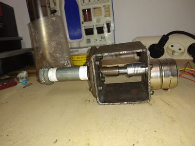
1.1 Cut 70mm of structural square tube of 70mm by 70mm, you can use the angle grinder with metal cutting disc, this cube will serve as container and the chassis of the extruder.
1.2 Use the Drill with the 1"Saw Cup to make two holes perfectly aligned at the center of the cube.
1.3 Place and center the flange in one hole, mark down the points where the screws will be placed, Place the motor on the other hole, carefully center the axle on the hole and mark down the points where the screws will support the motor.
1.4
2.Installing the electrical system
Install the heating element, the heat sensor and motor wiring, this is connected to the machine's controller board.
3.Mechanical efficiency test
From the computer, send commands to the controller board to verify th correct movemente of the pellets inside of the extruder, verify the speed and strengh requirements.
4.Thermal efficiency test
From the computer, send commands to the controller board to verifythe heating elemente performance and define the optimal temperature to melt the plastic and make it flow though the tube.
5.Material flow test
Heat the extruder to the work temperature obtained before, and define the motor's speed to produce a continuos string of plastic as fast as possible, maintaining the diameter and the material properties. In this step the lenght and material's retraction time are calculated, to get total control of the extrusion during an impression.
6.3D Printer integration
Use the temperaute and displacement data to adjust the printer firmware parameters, this will be integrated to the machine and will always work as a normal extruder, the data will be used too in the software "slic3r" to generate G codes for the machine in different tempetature, speed, work acceleration and retraction, make some test to adjust the settings in different models.
Avances Adicionales
10/06/2019
Since the first assembly of the extruder, we used a Nema 17 motor with 2,2kg/cm Torque and 1:50 gearbox, which presented printing failures and loss of steps due to overheating, which also affected printing speed, something visible in the quality of the printed pieces, to solve this problem the motor has been replaced with a Nema 23 with 9 kg/cm torque and 1:72 gearbox, after the software adjustements and some tests, the extruder presented a better speed and acceleration development, and a better print quality.
23/05/2019
- We take as a fact that a big volume print is expensive and take a long time, until this moment we have achieved the right development of the Pellet Extruder using PLA pellets, which reduce the prinitng cost to one tenth in comparison with filament printing methood.
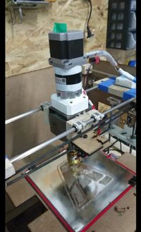
To solve the printing time problem a variable volume printing nozzle has been designed, it's a extrusion tip that doesn't have a specific diameter orifice, it has a 1x1 cm groove. this one has a moving part that controlls the material output in different times of the print. The operation principle is the same that an Industrial Type Plastic sheet Extruder has, but simplified to be installed in a moving shafts system. The action strategy of this printing Tip is that when it is making outer perimeters the nozzle closes to let out a 1x1mm filament, that's how we can make the outer layers with good level of detailing, in the moment of filling the piece it opens up to 10mm and performs the work at least 6 times faster than a conventional extruder and when it is executing the displacements, it closes completely to avoid unwanted intrusions before reaching the work coordinates.
24/06/2019
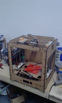
- Se ha construido una segunda impresora que se usara exclusivamente para el desarrollo del extrusor laminar, esta tiene un volumen de impresion de 300X400x300mm y se ha construido con materiales reciclados de muebles, una caja de whiskey para el extrusor, motores extraidos de una fotocopiadora, se usaron latas de cerveza y material resistivo extraido de una tostadora vieja para el elemento calentador del extrusor.
En la punta del extrusor se ha instalado un motor paso a paso con reductor, el cual mueve una puntilla a lo largo de una ranura de 10mm de ancho y 1mm de grosor, este mecanismo se ha construido totalmente a mano con la ayuda de un motortool y un taladro manual.
Estado del Proyecto
10/06/2019
- Se han diseñado las piezas de la impresora, para reemplazar las provisionales de madera, la maquina creara estas piezas la 2da semana de Junio
20/05/2019
- Se estan haciendo simulaciones en Grasshopper de Rhinoceros para la generación del Gcode.
- Se han hecho pruebas de postproceso con lenguaje Perl en Slic3r para generación de Gcode.
- Se necesita de un profesional con conocimiento en matematicas y programación para generar los codigos que haran funcionar el extrusor correctamente
24/06/2019
- Se ha encontrado un metodo temporal de generar gcode para pruebas de la maquina con software CNC y un poco de edicion manual de los archivos gcode.
- Se necesita de un profesional con conocimiento en matematicas y programación para generar los codigos que haran funcionar el extrusor correctamente.
